InSky OPGW
Used by electric utilities on transmission lines with the voltage of 35 kV and higher for creating optical communication lines and protecting the power lines from lightning strikes.
InAir ADSS
Applied for aerial installation on distribution and power transmission lines for building long distance optical communication systems.
Specialty Cable
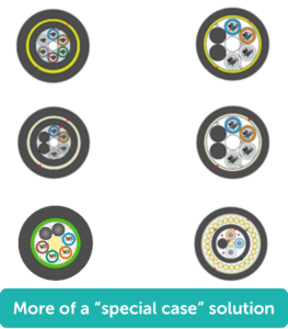
Used for distributed fiber optic sensing in different applications.
InFire Rated
Used for indoor and outdoor applications where fire resistance is a must. Remain functional under direct flame for at least 180 minutes.
InDuct
Applied in ducts, conduits and trays with no risk of rodent attacks. Can also be lashed.
InArmor
Designed for high reliability in harsh environments with potential mechanical impact. Applied in all ground types, swamps, and harsh rivers.
BlownIn
Designed for air blowing in ducts and microducts for building reliable underground communication networks.
InWater
Designed for underwater application with increased crush and tensile loads.
InAir Figure 8
Used for cost-effective one-step aerial installation mostly in rural areas where the spans between poles are not long .
InControl
Applied in substations for control purposes.
InHome FTTH
Used to create communication lines between the common distribution box and a location inside the building (including vertical runs), between entrances or corridors in office buildings.
InDrop FTTH
Applied for aerial installation on transmission towers, lightning poles, between buildings and structures for communication networks in rural areas.
Finding the right cable that best fits the specifications of a project can be a difficult task. For this exposition, we will approach cable selection by the application of the cable. The five main types we will discuss are transmission, distribution, substation, Fiber-to-the-Home (FTTH), and special cases.
Transmission
As we dig into transmission cables, we will focus on the main types for this application which are Optical Ground Wire (OPGW), All-Dielectric Self-Supporting (ADSS), Optical Phase Conductor (OPPC), Underground Cable, and Wrapped Dielectric:
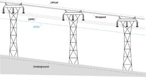
Optical Ground Wire
The Optical Ground Wire cable, or OPGW, is a type of cable used by the electric utility industry in the construction of electric power transmission and distribution lines. OPGW fiber optic cable combines the functions of:
— Grounding: the overhead ground wire shields the high-voltage conductors from lightning strikes and secures current flow in case of fault currents.
— Communication: the incorporated optical fibers allow long distance transmission of data at high speed.
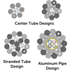
The fiber optic ground wire design typically consists of aluminum-clad steel wire and/or aluminum alloy wire protective layers with up to 432 fibers within the cable. This type of cable is suspended on power transmission lines with a voltage of 35 kV and higher.
Advantages:
— Conceptually easy to replace a conventional shield wire with an OPGW
— Proven technology
— Excellent availability
— Multiple sources
— Wide range of designs available to meet specific mechanical, electrical, and optical requirements
— Can expect service life of 40+ years
Disadvantages:
— Higher cost relative to dielectric cables (2x)
— Line outages to install
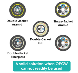
All-Dielectric Self-Supporting (ADSS)
InAir ADSS fiber optic cables are designed for outside plant aerial and duct applications and used in different installations (from pole-to-building to town-to-town).
When it comes to aerial deployments, ADSS fiber optic cables can provide a cost-effective and reliable solution. Fiber optic cables of this type are small and lightweight, yet they can withstand high loads and are flexible in applications. Additionally, the method of installation is fast and does not require a lot of special-purpose equipment.
Advantages:
— Conceptually easy to add an ADSS below the phase conductors
— Proven technology
— Excellent availability
— Multiple sources
— Wide range of designs available to meet specific mechanical, electrical (i.e. tracking-resistant), and optical requirements
— Very economical
— Can install without taking an outage
Disadvantages:
— Lower service life of 20+ years
— More vulnerable to damage than metallic cables
— Risk of damage from shotguns, birds, and squirrels
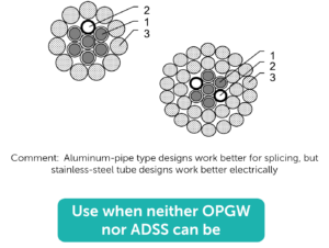
Optical Phase Conductor (OPPC)
InPhase OPPC (Optical Phase Conductor) is an optimal solution to provide redundancy in harsh conditions, such as long cable spans, crossings of cable spans, power lines with previously installed OPGW and ADSS and others. InPhase OPPC cable does not increase the load on support towers. It can be used as a backup or independent communication channel.
The main application of InPhase OPPC is the transmission of electrical power and construction of extensive optical communication system for data transmission.
Advantages:
— Intuitive to replace one or more standard phase conductors with OPPC
— A variation on the OPGW design concept
— Can expect service life of 40+ years
Disadvantages:
— Higher cost relative to dielectric cables (2x)
— Limited applications to date
— Access to the fibers much harder
— “Hot” enclosures or “optical isolator (insulator)”
— Difficult maintenance (splices)
— “Double whammy” of isolator failure
— Lose both communications and power transmission
— Coordinating sag with non-OPPC’s
— Line operating temperature limited to 85°C (185°F) (Max sustained fiber temp)
Underground Cable
When it is not possible to suspend the cable on overhead towers or install it into cable ducts, cable can be buried in any ground types, swamps, and harsh rivers.
Advantages:
— Proven technology
— Excellent availability
— Multiple sources
— Wide range of designs available to meet specific project requirements
— Duct, Direct Bury (armored), micro-duct/blown in
— Can install without taking an outage
— Good service life of 25+ years
Disadvantages:
— More vulnerable to damage than you first think
— Backhoes outnumber tornados
— Those pesky rodents
— High installation cost (but cable itself is very economical)
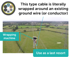
Wrapped Dielectric
Advantages:
— Conceptually easy to wrap a cable around an existing ground wire
— Theoretically, a great retrofit option
Disadvantages:
— Much lower service life, maybe 10 years
— Utilities have accepted < 5 years
— Very vulnerable to damage because cable must be small and light è low protection
— Shotguns, birds, and squirrels
— Short reel lengths = more splices = splice loss and cost
— “Bunching” of cable at mid-span over time
— Can lead to increased attenuation
— Very limited suppliers
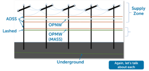
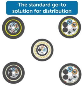
Distribution
The main types of transmission cables are All-Dielectric Self-Supporting (ADSS), Lashed Cable, Figure-8 Cable, Underground Cable, Optical Neutral Wire (OPNW), and Optical Messenger Wire (OPMW) or Metallic Aerial Self-Supporting (MASS). Many of these cable types were previously covered in Transmission portion of this reading so we will focus on the advantages and disadvantages for each cable as it pertains to the the distribution application.
All-Dielectric Self-Supporting (ADSS)
Advantages:
— Conceptually easy to add an ADSS in either the supply or communication zones
— Proven technology
— Excellent availability
— Multiple sources
— Wide range of designs available to meet specific mechanical and optical requirements
— Very economical
— Can install without taking an outage
Disadvantages:
— For distribution, none
— But, beware of shotguns, birds, and (especially) squirrels
Lashed Cable (Communications Region)
A “lashed fiber optic cable” is a system where a fiber optic cable is bundled to a separate support wire, called a messenger wire, using a spiral-wrapped stainless steel lashing wire.
Advantages:
— Can use any dielectric cable type that you would use in a duct
— Can use armored cable to help mitigate shotgun, bird, and squirrel damage
— Excellent availability with multiple sources
— Cable itself is very economical
— Wide range of designs available
— Can install without taking an outage
— Can use telco installation crews instead of power crews
— Can over-lash to add capacity
— Good service life of 20+ years
Disadvantages:
— Potentially very high make-ready costs
— Could be $50,000/mile or more (yikes!)
— Higher installation and O&M costs
— 2-step install: messenger, then cable
— Broken lashing = constant maintenance
— Messenger must be bonded to ground
— Induced voltage and current on metallic-armored cables
— Competition for space with telcos
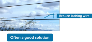
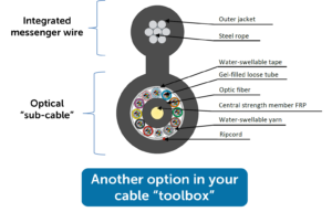
Figure-8 Cable (Think “Pre-Lashed”)
InAir Figure 8 Cables are overhead fiber optic cables with an external strength member used for cost-effective building aerial communication systems mostly in rural areas, where towers are located close to each other. Unlike all-dielectric self-supporting cables, where the strength member is placed in the core of the design, in Figure 8 cables the strength element is placed outside the core. The cross-section of this cable type is 8-shaped: the upper part is the suspension element, the lower one is the core with the fiber.
Advantages:
— Can install without taking an outage
— Can (perhaps) use telco installation crews instead of power crews
— Can over-lash to add capacity
— Integrated messenger means no broken lashing wires
— Can armor the optical core to help mitigate shotgun, bird, and squirrel damage
— “Not bad” economics
— Good service life of 20+ years
Disadvantages:
— Potentially very high make-ready costs
— Could be $50,000/mile or more (yikes!)
— Higher installation cost than ADSS
— Slower to string because of the shape
— Slower to splice prep because must remove the integrated messenger wire
— Messenger must be bonded to ground
— Competition for space with telcos
Underground Cable
Advantages:
— Proven technology
— Excellent availability
— Multiple sources
— Wide range of designs available to meet specific project requirements
— Duct, Direct Bury (armored), micro-duct/blown in (will explain later)
— Can install without taking an outage
— Good service life of 25+ years
Disadvantages:
— More vulnerable to damage than you first think
— Backhoes outnumber tornados
— Those pesky rodents
— High installation cost (but cable itself is very economical)
Optical Neutral Wire (OPNW)
A variation of OPGW and OPPC.
Advantages:
— Intuitive to replace a conventional neutral with an OPNW
— Can expect service life of 40+ years
Disadvantages:
— High cost relative to dielectric cables (2x)
— Limited applications to date
— Usually, it is easier to use ADSS
— Requires new supporting hardware and changes to work practices (some folks don’t like change)
— Must distinguish between standard neutral and OPNW (easy, but different)
— The reality of voltage and current on an OPNW
— “Hot” enclosures or “optical isolator (insulator)”?
— Again, different work practices

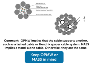
Optical Messenger Wire (OPMW) / Metallic Aerial Self-Supporting (MASS)
An optical messenger wire is an integrated supporting strength member in an aerial fiber optic cable that prevents the cable from sagging and supports long-distance installations on utility poles.
Advantages:
— Intuitive to replace a conventional messenger wires with an OPMW or MASS
— A variation on the OPGW, OPPC, OPNW design concepts
— Great resistance against shotguns, birds, and squirrels
— Can be over-lashed to add capacity
— Can expect service life of 40+ years
Disadvantages:
— Higher cost relative to dielectric cables
— Limited applications to date
— Usually, it is easier to use ADSS or lashed options
— Must distinguish between standard messenger and OPNW or MASS (easy, but different)
— Beware of induced voltage and current!
— Must bonded to ground
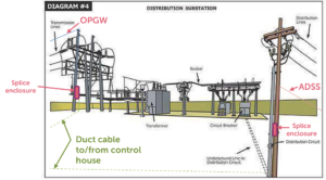
Substation (SS)
Common practice
— Aerial cables come into the SS to a splice point, and duct cable from there to control house
— All-dielectric underground cables in conduit typical
— ADSS can also be used
— Metallic armored cables NOT used because of induced voltage and current
Consider
— Non-metallic armored cables could be used for direct bury or better protection against rodents
— Micro-ducting could be used to add capacity to existing ducts or to allow for increasing capacity in the future
— Newer designs to support sensing, data acquisition, and advanced control systems for Smart Grid
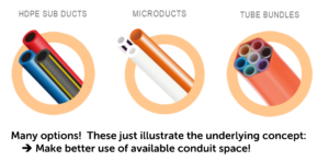
Microducts
Microducts provide an ideal, future-proof solution for deploying fiber optic cables within high-voltage substations, offering essential protection from the harsh electrical environment. The small, flexible conduits allow for faster and more efficient installation, future network expansion, and reduced maintenance costs.
Fiber to the Home (FTTH)
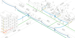
Cables up to the curb
— Any of the cables we have discussed for Distribution applications can be used for a FTTH network.
— Which type to use is up to you based your assessment of the advantages and disadvantages as applied to your service territory.
— The fiber counts to use will follow from your network architecture (density is a factor).
Drop cables
—Aerial
— Round
— Flat (“butterfly”)
— Figure-8
— Underground
— Same options as above, but…
— Conduit versus Direct-Bury
— Flat (“butterfly”) Cable
— The most popular option by far (≈ 90%)
— Easiest to prep of these three options
— Widely available “universal” hardware
—Figure-8 Cable
— The next most popular (≈ 6 – 7%)
— More use in rural settings where longer aerial spans are needed
— Hardware should be blessed by cable manufacturer
—Round Cable
— The least popular (≈ 2 – 4%)
— Prepped like any round cable/considered the hardest
— Capable of the longest spans (think “micro ADSS” designed to your specs)
— Dead-ends must be blessed by cable manufacturer
Note that you can add “toneable” capability to any of the above (using a tracer wire)
Direct Bury vs Conduit
Direct Bury
— Lower overall cost
— Multiple options for armor to protect cable
— Will need to ground/potential to carry voltage back to electronics
— Armor can used to locate cable after install
Conduit
— Higher overall costs
— Conduit provides protection for cable
— Can make repair/replace faster too
— No grounding necessary
— Can use ADSS cable in duct
— Can install multiple ducts for later expansion or leasing opportunities
— Ability to utilize micro-duct to run multiple micro-cables in same conduit (more opportunity to make $$$)
Special Situations
From an old advertisement: “Hold the pickles, Hold the lettuce, Specialty cables don’t upset us, All we ask is that you let us, make them your way!”
— Sensing. Using a fiber optic cable, there’s a way to sense and collect data on just about anything you could imagine
— Submersible. Need to get across a lake or river? There are submersible cable designs readily available!
— Add Power! Need both fiber and power in the same cable? It can be done!
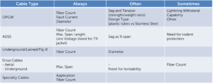
What Drives Cable Design?
To learn more about how our cable solutions apply to your project, contact our sales team: sales@incabamerica.com
View our current webinar library
View our current webinar library
Optical Fiber performance can be broken down into two key factors: Attenuation and Dispersion.
Attenuation
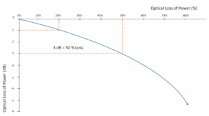
Attenuation is the loss of signal strength over distance. It impacts the ability of the receiver to receive sufficient power to properly process the signal. It is expressed in decibels of power loss (dB) per unit distance. It is most common in the industry to use dB/kilometer (km), but here in the US, dB/mile or dB/1000 ft are used.
Decibel loss can significantly reduce the efficiency of a cable as the “divorce law” states for every 3dB loss of optical power, you lose 50% of what you had before.
Attenuation has two components: intrinsic and extrinsic.
Intrinsic Attenuation is the loss of signal strength from internal influences. The two main causes of intrinsic attenuation are absorption and Rayleigh scattering.
Absorption is when a photon will give up kinetic energy when it interacts with an electron and excites it to a higher energy level.

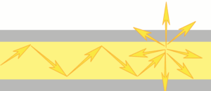
Raleigh Scattering is when light is scattered as the result of inhomogeneities and defects in the glass. These imperfections are microscopic and happen during production.
Extrinsic Attenuation is the loss of signal strength from external influences. The two main casues of extrinsic attenuation are Macrobends and Microbends.
A Macrobend is caused by a large-scale bend of the fiber which is visible and less than the fiber’s safe minimum bending radius.
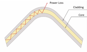
This type of loss is generally reversible once the bend is removed.
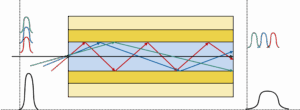
A Microbend is a small-scale distortions in the geometry of the fiber core. It can be caused during the manufacturing process, or by fiber “cross-overs” inside a tube.
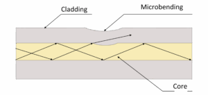
A microbend is usually reversible, unless the core has been permanently deformed.
Dispersion
Dispersion is the spreading out of a light pulse as it travels through a fiber. There are three types of dispersion: Chromatic Dispersion, Modal Dispersion, and Polarization Mode Dispersion (PMD).
Chromatic Dispersion is the phenomenon of pulse spreading due to the different colors of light (wavelengths) travelling at slightly different speeds through the fiber.

Modal (a.k.a. Intermodal) Dispersion in Multimode (MM) Fiber is the spreading of signal pulses as they travel down the fiber (May cause pulses to overlap as they arrive at the receiver, and cause bit errors)
Polarization Mode Dispersion (PMD)
Single-Mode optical fiber consists of one propagation mode, which in turn, is comprised of two orthogonal polarization modes, as shown in the graphic below. Asymmetrical differences in the fiber introduce small refractive index variations between the two modes. This is known as birefringence. This is caused by ovality of the core caused by a few different factors: the manufacturing process, internal stress (cabling), and external stress. Combating PMD becomes very important as transmission speeds increase.

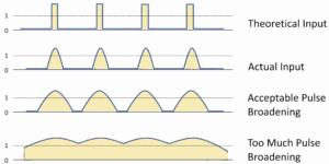
Dispersion leads to bit error; The graphic below illustrates how dispersion impacts the pulse input. Higher dispersion makes it harder to discern between the 0s and 1’s:
Applying the Performance Factors
Attenuation – recall: loss of signal strength
Typical maximum, individual, final values for single-mode fiber
Typical maximum, individual, final values for Multimode Fiber
Dispersion – recall: spreading of signal pulses. Overwhelmingly from the fiber manufacturing process
Therefore, typically not affected by the cable design or manufacturing processes
Advanced Fiber Types
Increases in bandwidth demand and transmission distances have led to two special types of single-mode (SM) fiber:
Non-Zero Dispersion Shifted (NZDS) SM Fiber:
Utilized to correct Chromatic Dispersion through controlling how light bends. This is similar to how eyeglasses are used to correct vision. The standard fiber is ITU-T G.655
NZDS Fiber is designed for use with Dense Wavelength Division Multiplexing (DWDM) to boost bandwidth which allows for higher data rates to be transmitted at a longer distance:
Data Rates:
Transmission Distances:
Cut-Off Shifted SM Fiber or “G654” SM Fiber:
An “ultra-low-loss” type fiber that was originally used for transoceanic submarine cables. The current G.654.E fiber allows even higher data rates: 400 Gbit/s up to 1 Tbit/s. Additionally, it allows for data to be transmitted at even longer distances too: Up to 900 km (560 miles). Essential for keeping the world connected.
Optimized for use between 1550 – 1625 nm
Typical attenuation limits: