InSky OPGW
Used by electric utilities on transmission lines with the voltage of 35 kV and higher for creating optical communication lines and protecting the power lines from lightning strikes.
InAir ADSS
Applied for aerial installation on distribution and power transmission lines for building long distance optical communication systems.
Specialty Cable
Used for distributed fiber optic sensing in different applications.
InFire Rated
Used for indoor and outdoor applications where fire resistance is a must. Remain functional under direct flame for at least 180 minutes.
InDuct
Applied in ducts, conduits and trays with no risk of rodent attacks. Can also be lashed.
InArmor
Designed for high reliability in harsh environments with potential mechanical impact. Applied in all ground types, swamps, and harsh rivers.
BlownIn
Designed for air blowing in ducts and microducts for building reliable underground communication networks.
InWater
Designed for underwater application with increased crush and tensile loads.
InAir Figure 8
Used for cost-effective one-step aerial installation mostly in rural areas where the spans between poles are not long .
InControl
Applied in substations for control purposes.
InHome FTTH
Used to create communication lines between the common distribution box and a location inside the building (including vertical runs), between entrances or corridors in office buildings.
InDrop FTTH
Applied for aerial installation on transmission towers, lightning poles, between buildings and structures for communication networks in rural areas.
7 August 2025
Optical Fiber performance can be broken down into two key factors: Attenuation and Dispersion.
Attenuation
Attenuation is the loss of signal strength over distance. It impacts the ability of the receiver to receive sufficient power to properly process the signal. It is expressed in decibels of power loss (dB) per unit distance. It is most common in the industry to use dB/kilometer (km), but here in the US, dB/mile or dB/1000 ft are used.
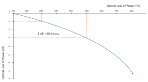
Decibel loss can significantly reduce the efficiency of a cable as the “divorce law” states for every 3dB loss of optical power, you lose 50% of what you had before.
Attenuation has two components: intrinsic and extrinsic.
Intrinsic Attenuation is the loss of signal strength from internal influences. The two main causes of intrinsic attenuation are absorption and Rayleigh scattering.
Absorption is when a photon will give up kinetic energy when it interacts with an electron and excites it to a higher energy level.

Raleigh Scattering is when light is scattered as the result of inhomogeneities and defects in the glass. These imperfections are microscopic and happen during production.

Extrinsic Attenuation is the loss of signal strength from external influences. The two main casues of extrinsic attenuation are Macrobends and Microbends.
A Macrobend is caused by a large-scale bend of the fiber which is visible and less than the fiber’s safe minimum bending radius.
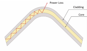
This type of loss is generally reversible once the bend is removed.
A Microbend is a small-scale distortions in the geometry of the fiber core. It can be caused during the manufacturing process, or by fiber “cross-overs” inside a tube.
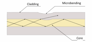
A microbend is usually reversible, unless the core has been permanently deformed.
Dispersion
Dispersion is the spreading out of a light pulse as it travels through a fiber. There are three types of dispersion: Chromatic Dispersion, Modal Dispersion, and Polarization Mode Dispersion (PMD).
Chromatic Dispersion is the phenomenon of pulse spreading due to the different colors of light (wavelengths) travelling at slightly different speeds through the fiber.

Modal (a.k.a. Intermodal) Dispersion in Multimode (MM) Fiber is the spreading of signal pulses as they travel down the fiber (May cause pulses to overlap as they arrive at the receiver, and cause bit errors)
Polarization Mode Dispersion (PMD)
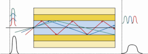
Single-Mode optical fiber consists of one propagation mode, which in turn, is comprised of two orthogonal polarization modes, as shown in the graphic below. Asymmetrical differences in the fiber introduce small refractive index variations between the two modes. This is known as birefringence. This is caused by ovality of the core caused by a few different factors: the manufacturing process, internal stress (cabling), and external stress. Combating PMD becomes very important as transmission speeds increase.

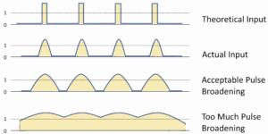
Dispersion leads to bit error; The graphic below illustrates how dispersion impacts the pulse input. Higher dispersion makes it harder to discern between the 0s and 1’s:
Applying the Performance Factors
Attenuation – recall: loss of signal strength
Typical maximum, individual, final values for single-mode fiber
Typical maximum, individual, final values for Multimode Fiber
Dispersion – recall: spreading of signal pulses. Overwhelmingly from the fiber manufacturing process
Therefore, typically not affected by the cable design or manufacturing processes
Advanced Fiber Types
Increases in bandwidth demand and transmission distances have led to two special types of single-mode (SM) fiber:
Non-Zero Dispersion Shifted (NZDS) SM Fiber:
Utilized to correct Chromatic Dispersion through controlling how light bends. This is similar to how eyeglasses are used to correct vision. The standard fiber is ITU-T G.655
NZDS Fiber is designed for use with Dense Wavelength Division Multiplexing (DWDM) to boost bandwidth which allows for higher data rates to be transmitted at a longer distance:
Data Rates:
Transmission Distances:
Cut-Off Shifted SM Fiber or “G654” SM Fiber:
An “ultra-low-loss” type fiber that was originally used for transoceanic submarine cables. The current G.654.E fiber allows even higher data rates: 400 Gbit/s up to 1 Tbit/s. Additionally, it allows for data to be transmitted at even longer distances too: Up to 900 km (560 miles). Essential for keeping the world connected.
Optimized for use between 1550 – 1625 nm
Typical attenuation limits: